In a previous experiment, where I was testing some of the LoRa modules from Reyax, I managed to communicate on a distance of 20 kilometers.
Inspired to go further, I embarked on a new journey to design and test a directional Yagi antenna that turned to be capable to communicate at 40 kilometers or even more—a feat that took me across country borders just to test the setup.

PCBWay offers services for custom PCBs, PCBA, 3D printing, CNC machining, Injection molding, and more.
Check out their shared projects section to explore ideas for your next project or order any of the already created PCBs from thousands of creators!
Tools and Materials
To construct the antenna, you'll need to gather some specific materials and tools. Start with a coaxial cable that has an SMA connector to connect the antenna to your LoRa board. You'll also need copper or similar metal rods. I used 2mm thick copper wire that I straightened and cut based on the antenna specs.
You may also need some super glue, soldering iron, wire strippers and a flush cutter. Below are links to some of the items that I used. These are affiliate links so when you buy through them, you support me and my channel at no extra cost for you!
- SMA Cable - https://s.click.aliexpress.com/e/_oCKzIPw
- RG58U Antenna Cable - https://s.click.aliexpress.com/e/_ok2Hc2g
- Wire Stripper - https://s.click.aliexpress.com/e/_oDTnss8
- Flush Cutting Pliers - https://s.click.aliexpress.com/e/_oDnmZ3I
- NodeMCU Microcontroller - https://s.click.aliexpress.com/e/_oF2nzGM
- Mini Breadboards - https://s.click.aliexpress.com/e/_okZle8Y
- Soldering Station - https://s.click.aliexpress.com/e/_olgLvfS
- Multimeter - https://s.click.aliexpress.com/e/_oFZ31NA
- Bench Power Supply - https://s.click.aliexpress.com/e/_olduGic
- Arduino Learning Kit - https://s.click.aliexpress.com/e/_oogVXdI
- 3D Printer - https://s.click.aliexpress.com/e/_opZmCZi
Reyax LoRa Modules:
Designing the Directional Antenna
The design of the antenna is a crucial step that lays the groundwork for achieving great performance and range. To start, we'll utilize the website "3G Aerial" to calculate the dimensions of our antenna elements based on the frequency we intend to use.
I entered 868Mhz for the antenna, 10mm for the boom size being square and 2mm diameter for the elements diameter. The calculated dimensions are below.
Javascript Version 2022-06-09 by 3G-Aerial,
based on Rothammel / DL6WU
Long-yagi DL6WU
-------------------------------------------------------------
Frequency f: 868 MHz
Wavelength λ: 345 mm
Element diameter d: 2 mm
Boom diameter D: 10 mm

Total number of elements: 5
Boom length: 235 mm
Gain: 10 dBi (approx.)
-------------------------------------------------------------
Reflector length R: 168 mm
Reflector position R = 0
-------------------------------------------------------------
Dipole length F: 159 mm
Dipole position F (R-F): 69.1 mm
Gap at connection point g <= 4.6 mm
-------------------------------------------------------------
Length D1: 151 mm
Director position D1 (R-D1): 95 mm
Distance F-D1: 25.9 mm
-------------------------------------------------------------
Length D2: 149 mm
Director position D2 (R-D2): 157 mm
Distance D1-D2: 62.2 mm
-------------------------------------------------------------
Length D3: 147 mm
Director position D3 (R-D3): 231 mm
Distance D2-D3: 74.3 mm
-------------------------------------------------------------
Driven element (dipole) form: Straight
Elements on a dielectric boom or on a metal one, but remote from it.
Boom-correction is not taken into account.
The antenna is composed of multiple elements: a reflector, driven element, and directors. The reflector sits at the rear, and its role is to reflect the signal toward the forward elements. The driven element, positioned next, is the active component that actually sends or receives signals. It needs to be split into two symmetrical parts with a small gap in between. Finally, in front of the driven element, we have the directors. These elements focus the beam to make the antenna more directional, enhancing its range.
Precision is key, so ensure the copper rods are cut to the exact lengths provided by the calculator. Establish the dimensions for each element: the reflector is the longest, while each subsequent director is slightly shorter. All elements must be placed accurately on the boom for optimal antenna performance.
To help me with positioning the elements as necessary, I designed and 3D printed the boom of the antenna with the holes in place.
3D Printed Antenna Boom
The 3D printed antenna boom is a crucial structural component that holds the various elements of your directional antenna in place. To start, you will need a 3D printer or the help of a 3D printing service to create this part. I designed the boom with specific holes and slots tailored to the precise dimensions needed for my copper rods, ensuring that each element sits securely and accurately aligned.
The boom consists of two printable parts: the handle and the main section where the reflector, driven element, and directors will be placed. After downloading the STL files available in the project resources, load them into the 3D printer software. Be mindful of the printer's size limitations; you may need to tweak the design if your printer's capacity is constrained.
After printing, the holes that I left in the model turned out to be slightly undersized as I did not left any tolerance so I had to use a drill to slightly enlarge them.
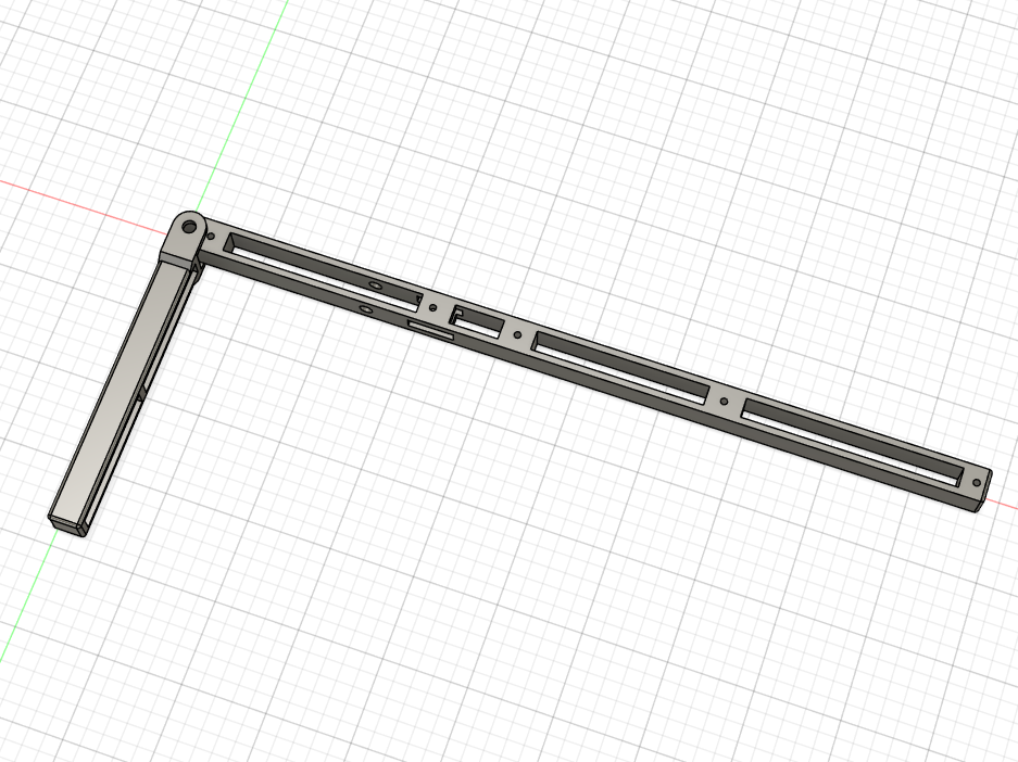
The antenna boom as designed in CAD
The model can be downloaded from here.
Building the Antenna
Building the antenna involves assembling all the parts with care to ensure everything is aligned correctly for optimal performance. Start by preparing your coaxial cable. You'll want to strip the cable using wire strippers to expose the inner signal wire and the outer shielding, which will connect to the driven element of your antenna.
Next, focus on the 3D printed parts, which include the handle and the boom of the antenna with pre-marked positions for each metal rod. Slide the copper rods through their designated holes on the boom. It's essential that these holes match the precise dimensions needed for optimal element performance. If they're too tight or too loose, you might need to adjust them manually using a drill for a better fit.
Once components are correctly positioned, secure everything in place. Start with the longer reflector at the back, move to the split-driven element, and finish with the directors. Use CA glue to fix each rod, being careful to avoid adding glue to the hinge. Ensure that the driven element is correctly split at the center with the specified gap. From there, thread the coaxial cable through your assembly, attaching the signal wire and shielding to each half of the driven element using solder for a secure connection.
Arduino Code
To control the communication I used NodeMCU microcontrollers. They are programmed with the Arduino IDE and the full code is available below.
Stationary Module
#include <SoftwareSerial.h>

#define RXD2 14
#define TXD2 12

SoftwareSerial mySerial(RXD2, TXD2);

String Message = "Hello from station- have fun!";
String content = "";
int counter = 0;

void setup()
{
  Serial.begin(115200);
  mySerial.begin(115200);
  delay(1000);
  pinMode(0, INPUT_PULLUP);
  pinMode(2, OUTPUT);
  digitalWrite(2, HIGH);

  writeToModule("AT+BAND=868000000");
}

void loop() {
  if (Serial.available()){
    Serial.println("Writing");
    content = Serial.readString();
    content.trim();
    Serial.println();
    writeToModule(content);
  }

  if (mySerial.available()) {
    String incomming = mySerial.readString();
      Serial.println(incomming);
    if (incomming.length() > 10) {
      String channel_ID = incomming.substring(incomming.indexOf('=') + 1, incomming.indexOf(','));
      Serial.println("Channel ID : " + channel_ID);

      String str = incomming.substring(incomming.indexOf(',') + 1);

      String msgLength = str.substring(0, str.indexOf(','));
      Serial.println("Message Length : " + msgLength);

      String str2 = str.substring(str.indexOf(',') + 1);

      String message = str2.substring(0, str2.indexOf(','));
      Serial.println("Message : " + message);

      //send confirmation message
      content = "Message pingback: " + message;
      sendLoraData(content, channel_ID.toInt());
    }
  }

  // When the button is pressed send the message to other module
  if (digitalRead(0) == LOW) {
    delay(1000);
    String data = Message + " - Count: " + counter;
    sendLoraData(data, 2);
    //increase counter on each send
    counter++;
  }
}

void writeToModule(String content) {
  content = content + "\r\n";
  char* bufc = (char*) malloc(sizeof(char) * content.length() + 1);
  content.toCharArray(bufc, content.length() + 1);
  mySerial.write(bufc);
  free(bufc);
  delay(100);
  readSerial();
}

void readSerial() {
  if (mySerial.available()) {
    Serial.println(mySerial.readString());
  }
}

void sendLoraData(String data, int address) {
  String myString = "AT+SEND=" + String(address) + "," + String(data.length()) + "," + data + "\r\n";
  char* buf = (char*) malloc(sizeof(char) * myString.length() + 1);
  Serial.println(myString);
  myString.toCharArray(buf, myString.length() + 1);
  mySerial.write(buf);
  free(buf);
}
Traveler Module
#include <SoftwareSerial.h>

#define RXD2 14
#define TXD2 12

SoftwareSerial mySerial(RXD2, TXD2);

#define TARGET_ID 1

String Message = "Hello from Traveler - SUBSCRIBE!";
String content = "";
int counter = 0;

void setup()
{
  Serial.begin(115200);
  mySerial.begin(9600);
  delay(1000);
  pinMode(0, INPUT_PULLUP);
  pinMode(2, OUTPUT);
  digitalWrite(2, HIGH);
}

void loop() {
  if (Serial.available()){
    Serial.println("Writing");
    content = Serial.readString();
    content.trim();
    Serial.println();
    content = content + "\r\n";
    char* bufc = (char*) malloc(sizeof(char) * content.length() + 1);
    content.toCharArray(bufc, content.length() + 1);
    mySerial.write(bufc);
    free(bufc);
  }

  if (mySerial.available()) {
    String incomming = mySerial.readString();
    if (incomming.length() > 10) {
      String channel_ID = incomming.substring(incomming.indexOf('=') + 1, incomming.indexOf(','));
      Serial.println("Channel ID : " + channel_ID);

      String str = incomming.substring(incomming.indexOf(',') + 1);

      String msgLength = str.substring(0, str.indexOf(','));
      Serial.println("Message Length : " + msgLength);

      String str2 = str.substring(str.indexOf(',') + 1);

      String message = str2.substring(0, str2.indexOf(','));
      Serial.println("Message : " + message);

      digitalWrite(2, LOW);
      delay(2000);
      digitalWrite(2, HIGH);
    } else {
      Serial.println(incomming);
    }
  }

  // When the button is pressed send the message to other module
  if (digitalRead(0) == LOW) {
    delay(1000);
    String data = Message + " - Count: " + counter;
    sendLoraData(data, TARGET_ID);
    //increase counter on each send
    counter++;
  }
}

void sendLoraData(String data, int address) {
  String myString = "AT+SEND=" + String(address) + "," + String(data.length()) + "," + data + "\r\n";
  char* buf = (char*) malloc(sizeof(char) * myString.length() + 1);
  Serial.println(myString);
  myString.toCharArray(buf, myString.length() + 1);
  mySerial.write(buf);
  free(buf);
}
Testing the Antenna Range
Figuring out where to test the antenna was one of the most difficult and challenging parts. For most parts, LoRa needs a clear eye of sight between the modules to be able to send and receive data, so I used a website called HeyWhatsThat to figure out what it is that I see from my balcony.
Luckily, I live on a hillside so there is quite a lot that I could see, but not everything is easily accessible as there are a lot of mountains around. After some looking, I figured out that there is a place in neighboring Greece that is directly on the road and it is about 40km away from my home.
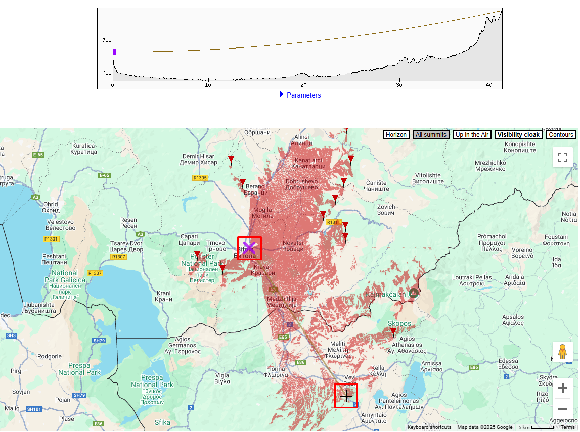
Output from HeyWhatsThat with the two locations marked
However, before going to a different country, I first made sure to go near by to one of the first locations that I tested LoRa range and I confirmed that the antenna works. That was on about 8km and the antenna worked perfectly.
I left one of the modules at home at my balcony and I programmed them in such a way that when the traveling module sends a message, if the stationary module receives that message, it sends it back as a confirmation to the traveling module. If we get a reply, we know that they can communicate and if we don't, then the station is out of range.
While at the close by locations, I also tried to test out the directionality of the antenna and I was pleasantly surprised to find out that it does not work when it is pointed away from the station.
The next day when I arrived on location in Greece, I connected the antenna, pointed it in the right direction and immediately I was greeted with the pingback message, meaning that both modules were able to communicate even though they are 40km apart.
For the sake of completeness, I also tried the original omnidirectional antenna that came with the RYLR993 module and I was pleasantly surprised to find out that it also works, at least on some of the tries. Being omnidirectional, I had to very specifically align it for the messages to go through but this still speaks a lot on the power of LoRa when we have clear eye of sight in between the two locations.
Using the Yagi antenna however, did not had any issues and as long as the antenna was pointed in the general direction of the station, all of the pingbacks came through and there wasn't a single time when there was even a hesitation in the communication.
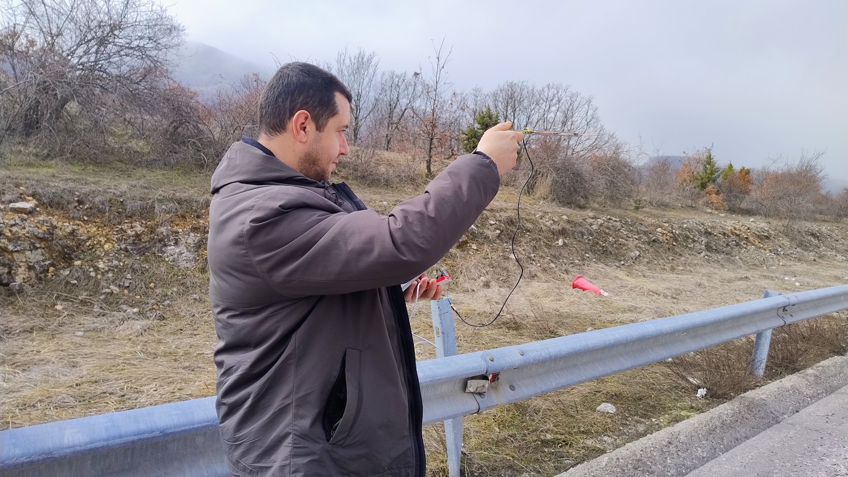
Me on location testing the DIY Yagi antenna
Quantitively Testing
I'm definitely an amateur when it comes to antennas as this is literally the first antenna of any sorts that I have build so far. At the moment, I don't know how, nor I have the tools to be able to test the antenna in a way that I can provide specs, confirm the approximated gain of the calculator nor knowing if I made a mistake that makes the antenna worse than it should be.
If you are a person that can test this, please if you have the time, make a copy of the antenna, test it out and reach out to let me know.
Challenges in construction
While making the antenna, one of the main challenges I faced was ensuring the precise alignment of the antenna elements—any deviation can impact performance. Drilling an accurate hole and securely fixing the copper rods is crucial. If the rods are misaligned due to incorrect measurements, you'll need to redrill or reposition them, which can be time-consuming.
Another common issue I had was with attaching the cable to the driven element of the antenna. I planned to have them mechanically connected, but that did not worked as expected so I had to solder the connections between the coaxial cable and the driven elements.
The soldering is not ideal as it can melt the surrounding plastic of the 3D printed parts.
Conclusion
Creating a functional directional antenna from inexpensive components and testing it to achieve a communication distance of 40 kilometers has been an incredibly rewarding experience.
My initial knowledge about antennas may be limited, but tools like the "3G Aerial" calculator have undeniably made the challenging aspects of this project much more accessible for anyone interested in experimenting.
I encourage everyone to try creating your own antenna and see how far you can push your communication range. Feel free to share your experiences and results so we can all learn together.
If you have any questions or need further guidance, don't hesitate to leave a comment. Also, consider subscribing to my YouTube channel where I provide more project videos and tips. I look forward to our next build together!