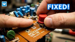
When working with SMD components, one of the key tools to have is a microscope. Unfortunately, I do not own one except for a small handheld one that I got years ago. It usually gets the job done for identifying components but it would have been super nice to have one where I can also show you what I'm looking at during repairs.
I know that at some point I will need to invest in one, but few days ago when I was moving some old stuff, I found a webcam that I had extracted from an old laptop and since the PCB was quite small, I came to the idea to add it to the handheld microscope and make it digital. I'm sure that it won't be the best option but it sounded fun and it will definitely make it better than how it is now.
This video is sponsored by Altium 365. Get your free workspace today and start transforming your design process today!
Tools and materials
Below are some affiliate links for items used on the project. When you purchase through them, you are supporting me and my channel without additional cost to you!
- Handheld optical microscope - https://s.click.aliexpress.com/e/_oFkCEfs
- Webcam - https://s.click.aliexpress.com/e/_oFb6TFM
- Assorted Resistors - https://s.click.aliexpress.com/e/_onLt8Vc
- 3D printer - https://s.click.aliexpress.com/e/_olXTtxM
- Soldering Station - https://s.click.aliexpress.com/e/_oCmKcOQ
- TP4056 Charging Module - https://s.click.aliexpress.com/e/_oCS7EDc
Or just buy it ready:
- Digital Microscope - https://s.click.aliexpress.com/e/_oDevHGO
Designing the Camera Mount
The first problem that I needed to solve was how to mount the camera module on to the microscope in such a way that the camera is mounted just a few millimeters from the lens. Since I've recently purchased a 3D printer, I immediately started designing a mounting bracket that I could print.
I started the process in Fusion 360, where I first drew the mounting piece that will clip onto the eye pieces of the microscope. I measured that and I added some small offset based on my print preferences.
From there, once I had the mounting piece, I drew another rectangle on top to house the camera PCB.
Of course, I did not managed to get a good fit on the first try but after few tries, I managed to get a mounting bracket that fits nicely on the microscope eyepiece, as well as holding the camera PCB at the right distance and straight down on it.
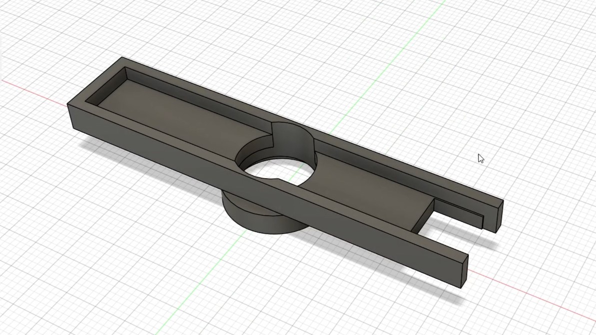
The final camera mount after few iterations
Upgrading the Power Source
One of the biggest drawbacks of the original handheld microscope was its reliance on small coin cell batteries. After the original ones got empty, I could not find thin enough batteries to replace them with so I was using larger ones and I had the cover glued to the case with electrical tape. This made the light a bit shimmery at times and it was not pleasant to be used.
To make the microscope more practical and eco-friendly, I decided to switch to a rechargeable lithium battery. I started by removing the old button cells and identifying the positive and negative terminals inside the microscope. Then, I tried to solder wires directly to the battery terminals but I failed at that so I had to open up the microscope to get access to the wiring inside.
Once inside, I soldered two wires, one to the switch, and another on to the negative side of the LED. I then routed these wires outside and I used a salvaged mini lithium battery with a TP4056 charger board. I soldered these wires to the charging board on the output terminals and before assembly, I made sure that it all works.
To secure the battery, I once again used some electrical tape as I was not able to design an enclosure that would fit in the existing grooves on the microscope. I know that this might be ugly, but it was fast and good enough for what I need.
Once I had the battery in place, I realized that the LED was too bright now, so I also added a 100 ohm resistor in series with the LED so that I make it less bright.
Testing the Microscope
To test the microscope, I first used some of the PCBs that I had laying around and I was pleasantly surprised by the image clarity and that I was able to read chip numbers without any issues. I then explored some other materials around me and below are few examples of the images that I'm able to extract from the microscope.
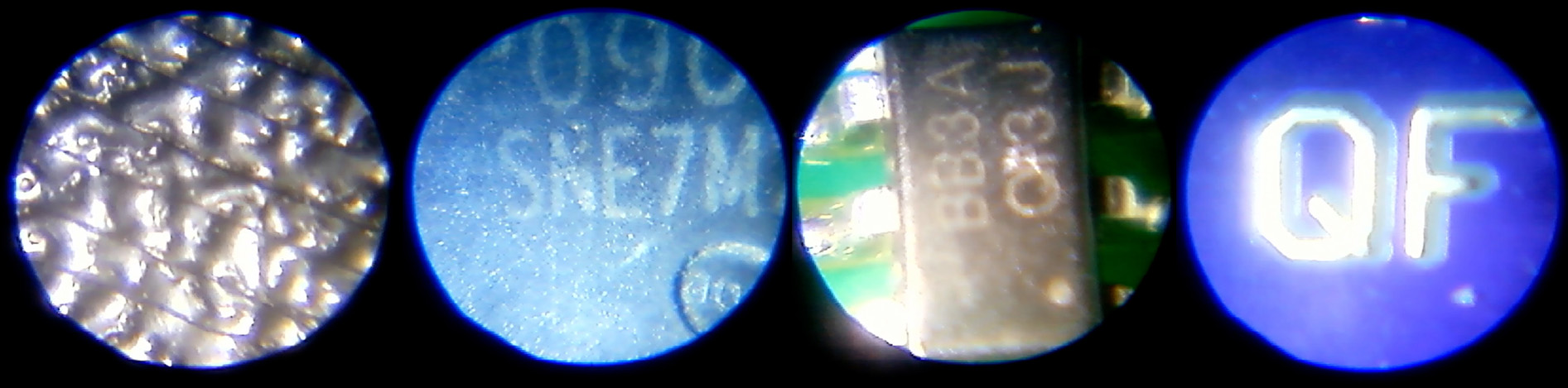
From left to right: 3D print lines on first layer, chip number from a BMS MOSFET, chip number from small SOT-23 component, solder mask alignment on PCB
Conclusion
Is this the best microscope there is? No, not at all. In fact, I'm not sure if it is worth the hustle to modify since digital microscopes got so cheap in recent years.
Was it a good exercise? Absolutely yes! With it I learned how to fit 3D printed parts around other objects, how to iterate with the 3D design process and I got a nice little tool along the way that I can now use to include PCB closeups in my videos and get chip numbers more easily then before.
I hope you found something to learn as well, and if you did, I'll ask you to subscribe to my YouTube channel for more projects and experiments in the future.