I very rarely revisit a project but this one is kind of a special one since several of my friends requested a variant of it for their home.
A while back, I made a pellet level monitor for my pellet stove, and after receiving a lot of interest from friends, I decided to improve it. The original version used ESPHome and Home Assistant, and the goal now is to made it standalone and accessible via a mobile app, even if you don’t have a smart home setup.
Additionally, since I want to potentially sell this, I'll need to figure out how to package it all and enclose nicely in a 3D printed enclosure.

Tools and materials for the sensor:
Below is a list of parts and support equipment to make the sensor. These are affiliate links so by purchasing through them, you are supporting me and my channel, at no extra cost to you!
Parts:
- VL53L0x Time of Flight sensor - https://s.click.aliexpress.com/e/_oCzQk7r
- NodeMCU Developement Board - https://s.click.aliexpress.com/e/_omtR6a5
Equipment:
- JCD Soldering Station - https://s.click.aliexpress.com/e/_oBQKqCv
- Digital Multimeter - https://s.click.aliexpress.com/e/_okMpnx3
- Bench Power Supply - https://s.click.aliexpress.com/e/_oF54b05
How It Works
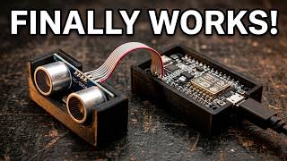
At its core, the sensor node uses a VL53L0X sensor to measure the distance to the pellets in my stove. The sensor sends this data to a NodeMCU (ESP8266) microcontroller, which then maps the distance to a percentage level based on the storage capacity of my pellet boiler. For example, if the sensor detects something closer than 5 cm, it registers as 100% full, and as the distance increases, the level drops accordingly to a maximum of 80 cm where I consider the tank to be empty.
This data is sent to the Arduino Cloud, where it’s displayed on a simple dashboard, and it can also be accessed on a mobile phone through the IoT Remote app. The app updates every 10 seconds, so I can check the pellet level from anywhere, even without a smart home system. It’s a straightforward yet effective way to keep track of my stove’s fuel levels!
Wiring
The wiring the VL53L0X sensor to the NodeMCU is straightforward. Here’s how I did it:
- Connect the VIN pin on the VL53L0X to the 3.3V pin on the NodeMCU.
- Connect the GND pin on the VL53L0X to the GND pin on the NodeMCU.
- Connect the SCL pin on the VL53L0X to the D1 (GPIO 5) pin on the NodeMCU.
- Connect the SDA pin on the VL53L0X to the D2 (GPIO 4) pin on the NodeMCU.
That’s it! These four connections are all you need to get the sensor talking to the NodeMCU. Once wired, you can upload the code and start measuring distances. Just double-check your connections to avoid any issues when powering it up!
Code
Below is the full code that is uploaded to the NodeMCU via the Arduino Cloud. There are references to external files but these are all generated by the Arduino Cloud editor once you generate your device and assign it a thing. Both distanceMM and level are defined as cloud variables of type int.
#include <Wire.h>
#include <VL53L0X.h>

#include "thingProperties.h"

VL53L0X sensor;

int mmValue;
float percentValue;

void setup() {
 // Initialize serial and wait for port to open:
 Serial.begin(9600);
 // This delay gives the chance to wait for a Serial Monitor without blocking if none is found
 delay(1500);

 // Defined in thingProperties.h
 initProperties();

 // Connect to Arduino IoT Cloud
 ArduinoCloud.begin(ArduinoIoTPreferredConnection);

 /*
   The following function allows you to obtain more information
   related to the state of network and IoT Cloud connection and errors
   the higher number the more granular information you’ll get.
   The default is 0 (only errors).
   Maximum is 4
 */
 setDebugMessageLevel(2);
 ArduinoCloud.printDebugInfo();

 Wire.begin(D2, D1);
 sensor.setTimeout(500);
 if (!sensor.init())
 {
  Serial.println("Failed to detect and initialize sensor!");
  while (1) {}
 }

 //high accuracy
 sensor.setMeasurementTimingBudget(200000);
}

void loop() {
 ArduinoCloud.update();
 // Your code here

 mmValue = sensor.readRangeSingleMillimeters();
 if (sensor.timeoutOccurred()) {
  Serial.print(" TIMEOUT");
 } else {
  distanceMM = mmValue;
  percentValue = map(distanceMM, 50, 800, 100, 0);
  if (percentValue < 0) {
   percentValue = 0;
  } else if (percentValue > 100) {
   percentValue = 100;
  }
  level = percentValue;
 }

 Serial.print("Distance: ");
 Serial.println(distanceMM);

 Serial.print("Level: ");
 Serial.println(level);
}
Enclosure
For the enclosure, I wanted something simple yet functional to protect both the VL53L0X sensor and the NodeMCU. The sensor must be separate from the microcontroller since the sensor will be inside a metal box and will not get WiFi reception if it is together with the NodeMCU.
Since I'm still learning 3D design, I started by finding a 3D model online for a screwable case designed for the VL53L0X sensor. However, it didn’t fit my sensor perfectly, so I modified the design. I increased the pillar size by 0.1 mm to ensure a snug fit and added a side hole for the cable instead of the back. This way, the sensor can sit flat on the stove lid without any issues. To mount the sensor, I used small neodymium magnets (5x5x1 mm). I designed holes in the case for the magnets, but the first version was too tight. After a few test prints, I settled on 5.2 mm holes, which fit the magnets perfectly with a bit of glue to secure them.
For the NodeMCU, I used another 3D model. While it worked well for prototyping, the licensing restricts commercial use, so I’ll need to design my own for future versions. It also sits the NodeMCU too close to the metal from the stove and the wire to the sensor exits above the WiFi antenna so I fear that it might be causing issues with connectivity. To fix this, I’ll need to adjust the design to ensure the antenna has enough space and the cable strain relief is improved.
Conclusion
And there you have it—a standalone pellet level monitor that’s both practical and easy to use! This project has been a fun remake, and I’m thrilled with how it turned out. The VL53L0X sensor and NodeMCU work seamlessly together, and the Arduino Cloud makes remote monitoring a breeze but not quite there yet as it is not easy and practical to set it up from a customer point of view.. While the current version is functional, I’m already thinking about improvements for the next iteration, like refining the enclosure design and exploring alternatives to the Arduino Cloud.
If you enjoyed this project or have any suggestions for improvements, I’d love to hear from you! Drop a comment below with your thoughts or questions. Don’t forget to subscribe for more DIY tutorials and updates on future projects. Thanks for following along, and I’ll see you in the next one—cheers!